Question
According to the manufacturer's published specifications on my IEPE accelerometer data sheet, a compliance voltage of 24-30 Volts is required. The built-in IEPE current source in my data acquisition system will only provide 18 Volts of power. Will my accelerometer be able to operate properly at 18 Volts?
Answer
The answer to your question is a qualified, "Yes," but the available g range may be something less than rated full scale accelerometer output. Let's quickly analyze the situation to determine what effect, if any, this has on your IEPE accelerometer performance.
First, what is meant by the term "compliance voltage"? Since IEPE accelerometers require a constant current regulator, the open circuit output voltage of the current regulator is referred to as the compliance voltage. The supply voltage is the input voltage to the regulator which is generally about 1 to 2 Volts higher (depending on the type of regulator used) than compliance voltage.
Here is how we can determine the usable range of the IEPE accelerometer. In order to accommodate a positive and negative swing, the input signal is biased at some level. The actual bias level is generally included on the calibration certificate and nominal bias voltage data available from the product data sheet. So, to determine our usable range, we need to know both the bias voltage and the compliance voltage.
To digress a bit, what exactly is the bias voltage? It is the DC voltage measured when the accelerometer is at rest and connected to the constant current power supply. Using the information detailed in the original question, let's assume our accelerometer has a sensitivity of 100 mV/g, requires 24 Volts excitation, has a bias of 14 Volts and that a compliance of 18 Volts is available.
First, we must determine the maximum negative swing:
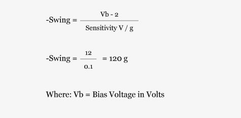
Since the 100 mV/g accelerometer has a maximum linear range of -50 g, or -5 Volts, -50 g will be the maximum range. In general, the negative range does not need to be calculated.
When computing positive range, a general "rule of thumb" is to simply subtract an additional 2 Volts from the compliance voltage. This additional factor will ensure that an accelerometer's integral electronics are operating well within the linear range. In some instances, only 1 Volt subtracted from the compliance voltage may be adequate. This will depend on the design of the power supply. The 2 Volt add-on was determined by testing a popular IEPE current source.
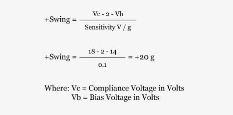
If this IEPE accelerometer was operating within the required 24 Volt range, it would have a full scale range of ±50 g (industry standard for a 100 mV/g accelerometer). If the user is measuring signals of <20 g, then 18 Volts of compliance range will be adequate.
This, however, is not the full story. The bias voltage is specified at room temperature. As ambient temperature changes, so does the bias voltage. The bias will increase inversely with temperature, so, in the previously referenced example, the maximum linear range of ±20 g may not be valid at higher or lower temperatures. Because of the bias drift, it is recommended that enough leeway be left to accommodate any anticipated temperature variations.
Below is a chart to assist in determining the maximum range of your IEPE accelerometer, based on both bias and compliance voltages. The chart will show the maximum expected undistorted output voltage. To determine the range in g's, simply divide the maximum undistorted output voltage (from the chart below) by the accelerometer sensitivity.
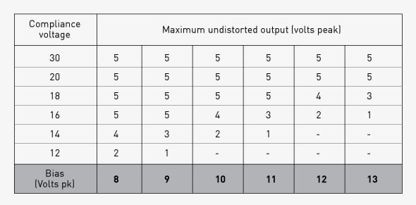
Example: What is the maximum level in g's of a 100 mV/g (0.1 V/g) accelerometer operating at 18 Volts compliance and 13 Volts bias? From the above table:

Note that the aforementioned chart assumes an output of ±5 Volts. It is always important to check accelerometer specifications, since some specialized units may have a different output voltage swing.
While reference was made to accelerometers, this same "rule of thumb" is applicable to any IEPE device, such as measurement microphones and force and pressure transducers.