Question
How do I make use of the Shunt Calibration feature for the
model 126?
Answer
The
model 126 has the ability to select the shunt cal (also known as RCAL) resistor at the simple press of the front panel button, "RSH".
The shunt cal resistor is placed in circuit for as long as the RSH button is depressed and is removed from the circuit, once the button is released.
The model 126 comes with a default shunt cal resistor in place, being approximately 30 k Ohms. Each channel has a similar shunt cal resistor in place, which is press fitted into single-leaded sockets – as located in photo #1. This resistor is easily removed and replaced with any, standard leaded resistor – no soldering is required.
Application of the shunt calibration resistor to a channel's circuit is selected from the front panel by pressing and holding RSH for each channel. The shunt calibration resistor is then applied to the bridge leg for as long as the RSH button is pressed. See front panel photo #2.
Also shown in Photo #1 is the location of Jumper 1 and Jumper 2. The jumper with a solder bridge applied is active. Jumper 2 is the default and this selection places the shunt resistor to the minus leg for a positive output voltage change when the RSH switch is pressed. Changing the jumper from 2 to 1 will have the opposite effect. (For jumper position 2, the shunt resistor is being applied from the input connector pin 4 and pins 6/8; for jumper position 1, the shunt resistor is being applied from pin 5 to pins 6/8. See Figure 1. Changing the position requires a soldering iron and a de-solder tool or solder wicking material. Simply heat the solder joint at position 2, remove the solder and applying a solder bridge to position 1.)
In many cases, the fastest method to find the correct shunt resistance value is with the use of a resistive decade box. Simply remove the resistor from the sockets and connect a resistive decade box to dial a resistive value to equal the desired full scale output, while pressing the RSH button.
This shunt cal test is typically used as an end-to-end verification test before and after a critical test is performed to verify a correct deflection voltage is observed, when applied and removed across a resistive bridge transducer. For the best proof of accuracy, the excitation voltage, gain, shunt resistance value and shunt calibration output voltage must be recorded before and after each test. Remember, shunt calibration is NOT a calibration, but it is a means of applying a resistance across a bridge leg to create a known voltage level that becomes a reference voltage value that is measured before and after a critical test to verify the accelerometer is connected and having a known output.
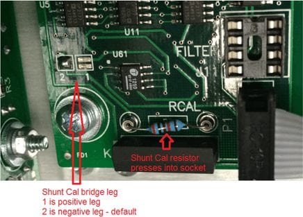
Photo 1
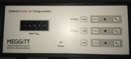
Photo 2
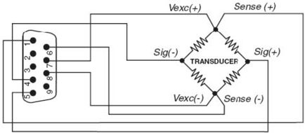
Figure 1