Question
Do you have connector assembly instructions for the
6917B cable with the replacement connector, 26574?
Answer
Assembly instructions are as follows:
1. Squarely cut through the cable at the end to be repaired. Strip the outer red ETFE insulation 0.5 inches and trim the shield as close as possible to the insulation. Remove all black low-noise treatment on the two leads (see TD 668A for proper lead preparation steps). Clean both leads with alcohol or other approved solvent. See figure 1.
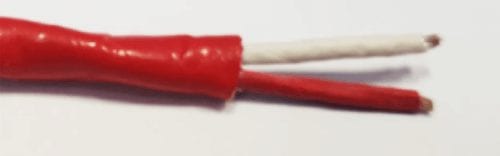
Figure 1
2. Disassemble the connector. Carefully cut the grommet in half – cut through one wall from O.D. to wire hole, over full length 180° apart.
3. Install the connector parts in order as shown in figure 2. (The fiberglass strain relief shown in figure 2 is not provided with the connector.)
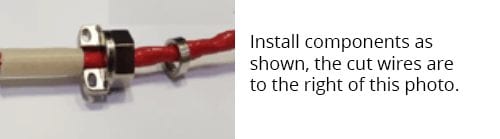
Figure 2
4. Strip off the insulation from each wire, 0.25", then insert the white insulator – do not tin the wire strands shown in figure 3.
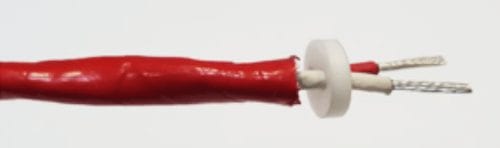
Figure 3
5. Crimp the contacts on the conductors, using crimp tool M22520/2-01 and select number 7 setting with Cannon K-18 stopper. (Tooling specified for this step in not provided with the connector. CAUTION: The crimp pins are not sold individually but as a kit with the connector!) See figure 4
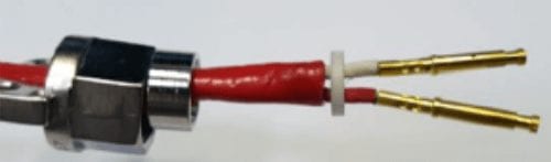
Figure 4
6. Measure insulation resistance with 100VDC, should be 1G Ohm minimum: Red wire to white wire and both wires to shield.
7. Install grommet halves in their proper location on the leads. Insert White lead into hole A and Red lead into hole B. See figure 5.
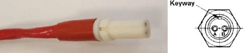
Figure 5
8. Install the assembly into the connector. Applying thread lock adhesive on the back shell is optional but recommended. Tighten the back shell to the connector as shown in figure 6. (Thread lock adhesive is not supplied with the connector and it should be rated to the full temperature of 500°F.)
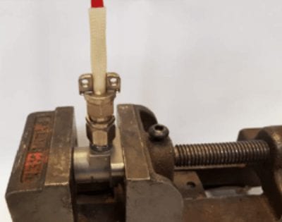
Figure 6
9. Install the cable clamp bar and screws. Again, thread lock adhesive is optional but recommended.
10. Verify continuity from Red lead at opposite end of cable to pin B and White lead to pin A. The reading should be approximately 1 Ohm, length dependent.
11. Measure insulation resistance per step 6 again.